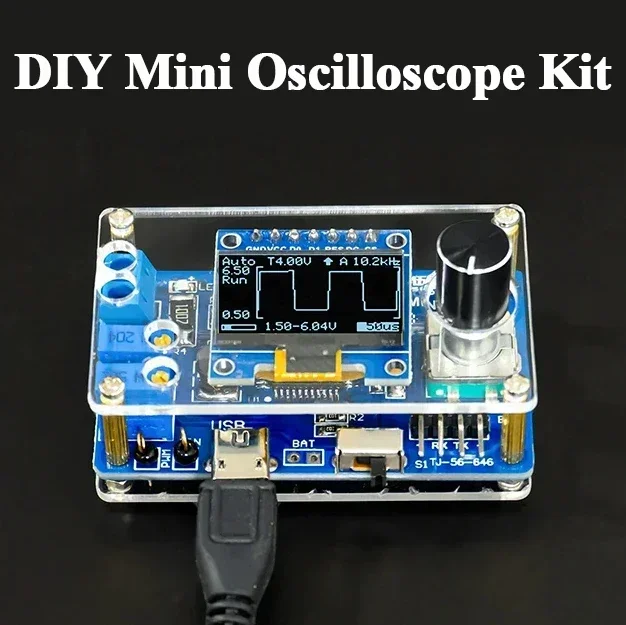
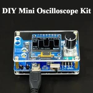
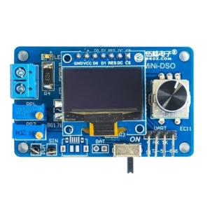
DIY Mini Digital Oscilloscope Kit STC8K8A Microcontroller Electronic Soldering Practice Loose Parts
$17.21 – $18.37Plage de prix : $17.21 à $18.37
Description:
- Condition: New
- Type: Voltage Regulator
- Origin: Mainland China
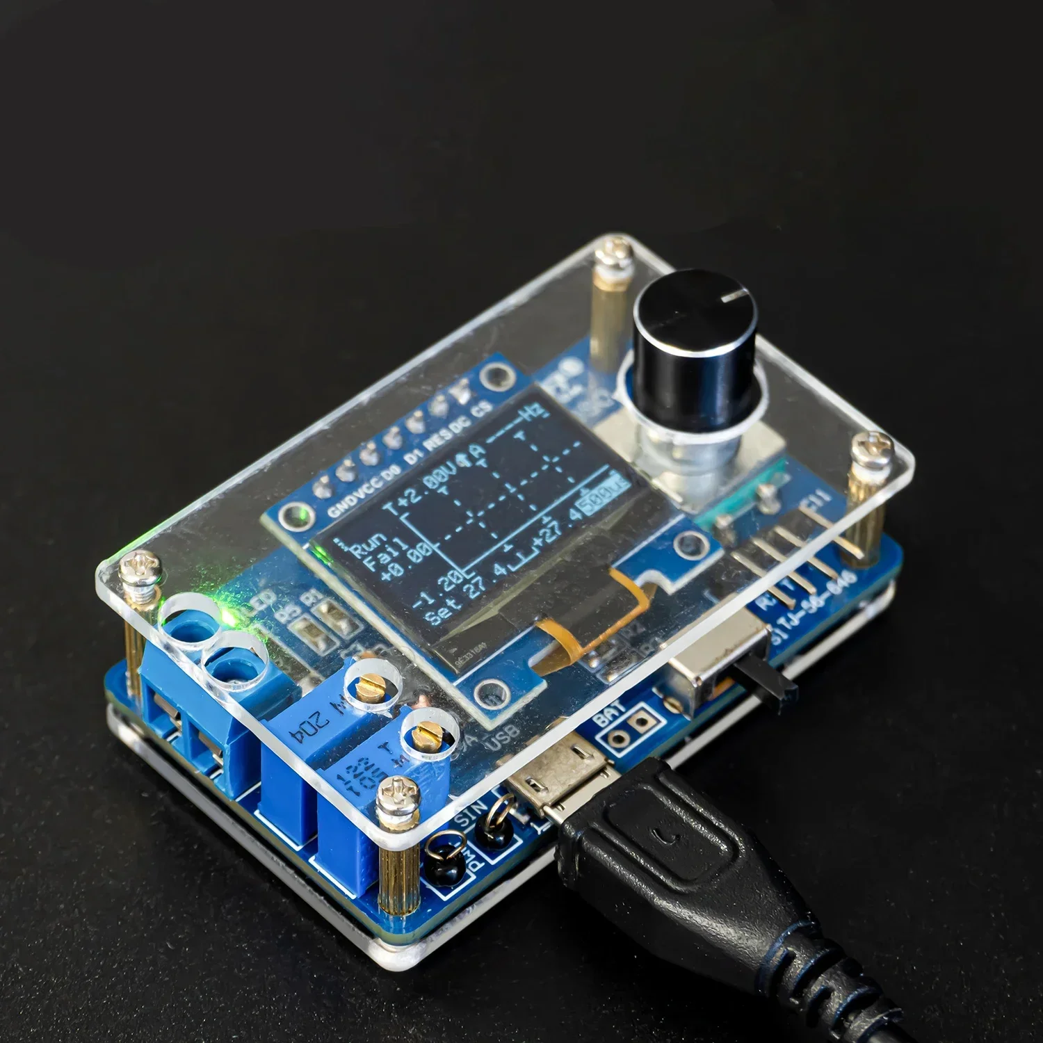
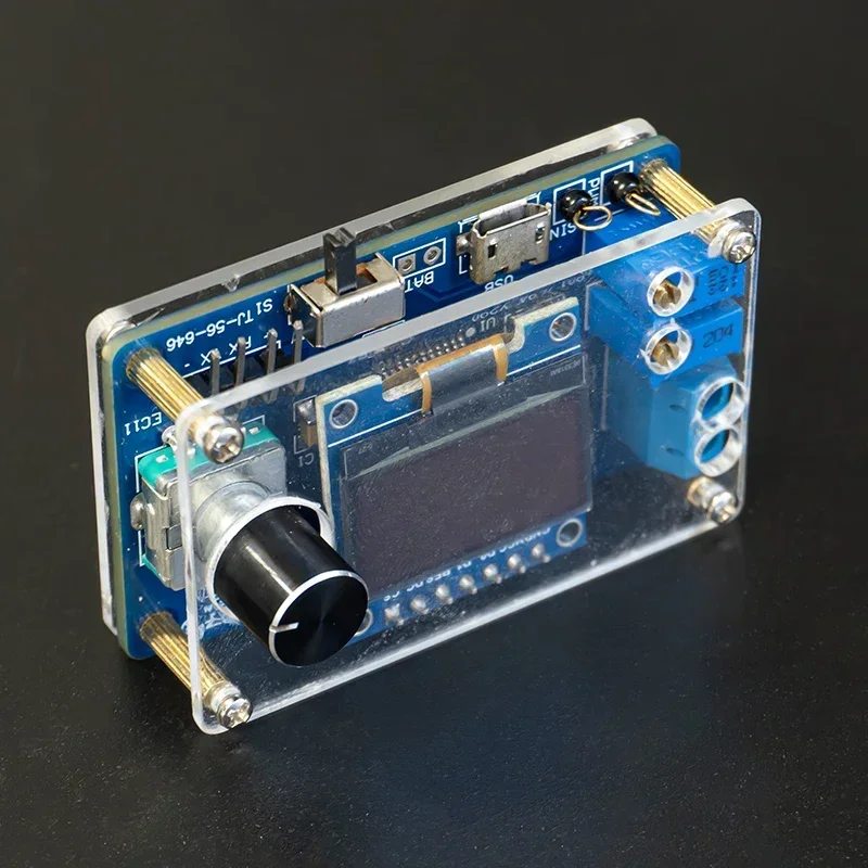
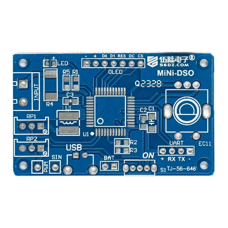
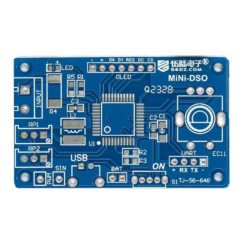
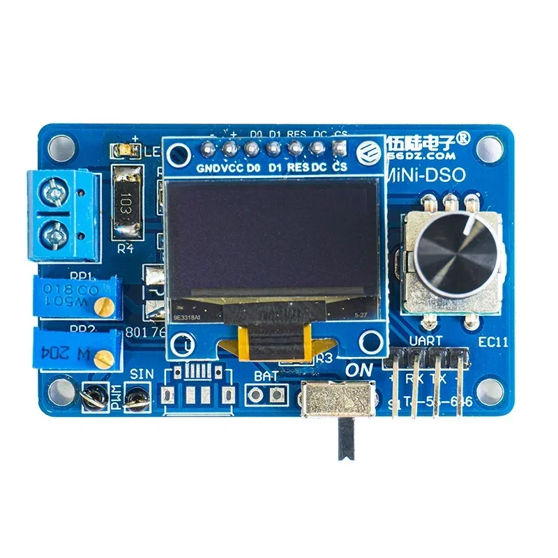
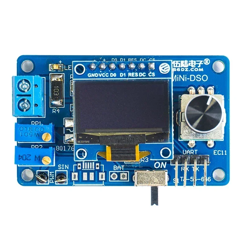
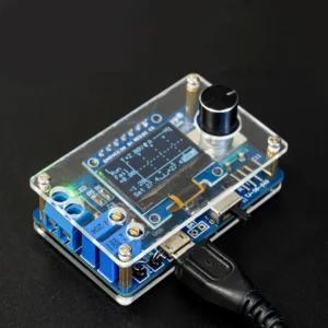
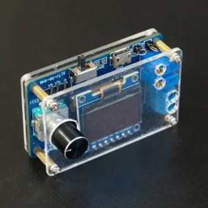
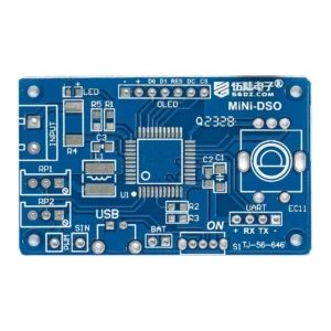
Product name: MiNi-DSO microcontroller oscilloscope kit
Product model: TJ-56-646
PCB size: 57 * 34mm
Working voltage: 4-5V
Single chip: STC8A8K64S4A12
Display: 0.96 inch OLED display screen -7P, 128 * 64 resolution
Number of channels: single channel
Sec/div: 500ms, 200ms, 100ms, 50ms, 20ms, 10ms, 5ms, 2ms, 1ms, 500us, 200us, 100us (100us only available in automatic trigger mode)
Voltage range: 0-30V
Sampling level: 10kHz@100us /Div
Trigger level: Trigger voltage level
Trigger slope: ↑ – rising edge, ↓ – falling edge trigger
Trigger mode: A-automatic mode, N-normal mode, S-single mode.
Product introduction:
This is a simple oscilloscope made with an STC8A8K microcontroller. It only requires a small amount of components and is easy to assemble. The function can cover simple measurements. This kit aims to build a basic oscilloscope model with the simplest possible principles and as little hardware as possible. The source code is easy to understand, and it is also very suitable for interested electronic enthusiasts to learn and research while using the product.
*Trigger level: For repetitive signals, the trigger level stabilises the display. For single-shot signals, the trigger level captures it.
*Trigger Slope: The trigger slope determines whether the trigger point is on the rising or falling edge of the signal.
*Trigger Mode:
*Auto Mode: continuous scanning. Click the encoder to stop or run sampling. If triggered, the waveform will be shown on the display and the trigger position will be placed in the centre of the graph. Otherwise, the waveform will scroll irregularly and display « Fail ».
*Common Mode: After the pre-sampling is completed, you can input the signal. If triggered, the waveform will be shown on the display, waiting for a new trigger. If there is no new trigger, the waveform will be kept.
*Single Mode: After the pre-sampling is completed, the signal can be input. If triggered, the waveform is displayed and the sampling is stopped. User needs single point encoder to start the next sampling.
*When in common mode and single mode, make sure the trigger level has been adjusted correctly, otherwise the waveform will not be shown on the display.
*Indicator light: Normally the indicator light is on to indicate that sampling is running.
*Save Setup: When exiting the setup interface, all parameters of the setup interface and main interface will be saved in EEPROM.
Circuit diagram:
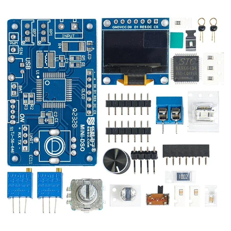
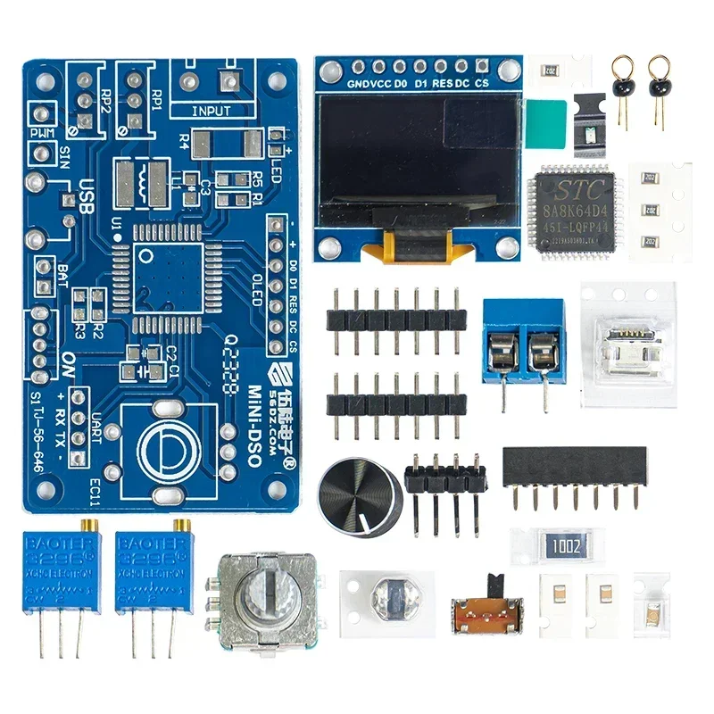
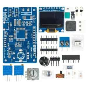
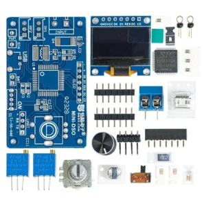
Package includes:
Function preview: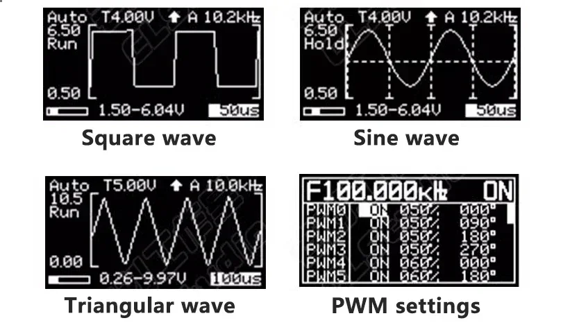

Soyez le premier à laisser votre avis sur “DIY Mini Digital Oscilloscope Kit STC8K8A Microcontroller Electronic Soldering Practice Loose Parts” Annuler la réponse
Produits similaires
Electronics Spare Parts
Computer CPU Cooling Fans for Acer Predator Helios 300 G3-571 G3-572 PH317-51 Fan Cooler Radiator
Electronics Spare Parts
Dimmers Dimming Unassembled Kit 100W DIY Suite Trousse Boards Switch Table Lamps 100 Watts
Electronics Spare Parts
Electronics Spare Parts
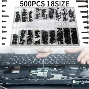
500Pcs 18 Types Screw Nuts DIY Kit Screw Driver Laptop Computer Assemble Repair Screws Fastener Set
Electronics Spare Parts
Electronics Spare Parts
Electronics Spare Parts









Avis
Il n’y a pas encore d’avis.